 ©
©
|
©
|
|
Back to the general motherboard/CPU info page You can bench-test the CPU/memory/motherboard assembly outside the case to confirm that everything's working, before you get too many complicating factors like drives and extra cards. Although I didn't actually do that myself, it's certainly a good idea, so I'm faking it for illustration purposes. : ) Most people will be using an add-in video card, so I'm covering that too. PCI-Express (PCIe) is the current standard for video card interfaces. Here's what the edge connector for PCIe x16 video cards look like. One row of pins, and the connector area is a bit slimmer than PCI or AGP: 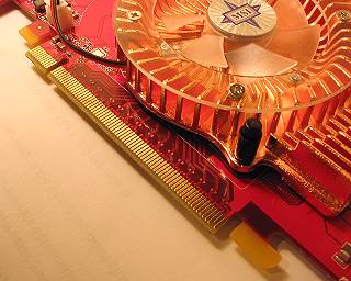 If you're building with old hardware that has an AGP video card, be aware that AGP cards have two rows of gold-plated contacts on their edge, unlike a PCI card that has just one row. 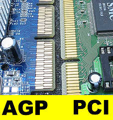 Since there are two layers of contacts inside the AGP slot too, it's possible to get the AGP card into the AGP slot only halfway, instead of all the way. Here's halfway. Notice that one row of gold contacts is still visible. The computer won't run like this. 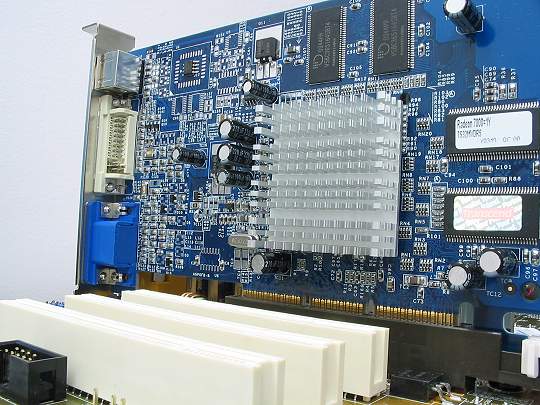 Now the AGP video card is fully seated into both the first and second layer of contacts in the AGP slot. No contacts are visible where the card meets the AGP slot. 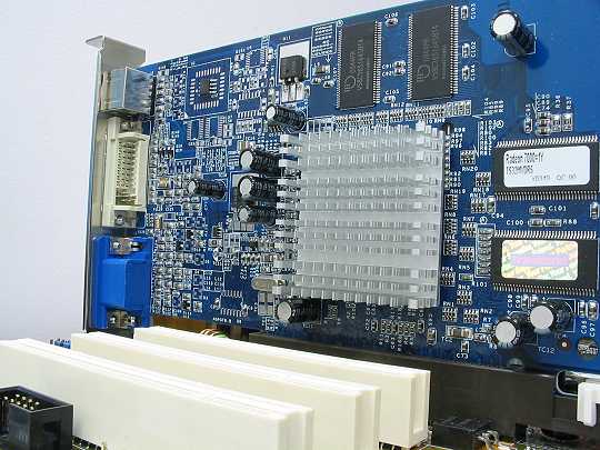 Cardboard makes a good bench-test surface, so I'm going to lay the motherboard right on its cardboard box, with the video card hanging off the end. I've added a keyboard, mouse, and monitor, and brought the case's ATX cable over to the motherboard. This motherboard doesn't use the ATX12V cable or other extra power cables, or I'd need them as well. Go back to the overview of cables if you need to refresh your memory. 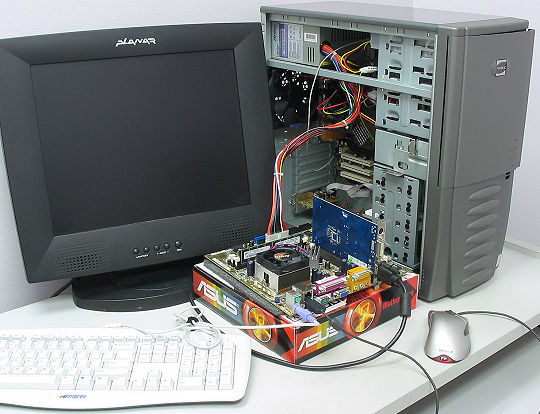 In this photo, I've got the case's power button plugged into the appropriate pins so I can send the motherboard and power supply a startup signal. The pins will vary, so consult your motherboard manual for the diagram if the markings on the motherboard aren't clear. 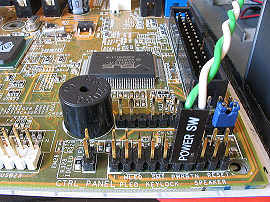 The system does a POST (Power-On Self-Test) and displays the processor's ID and the amount of memory. 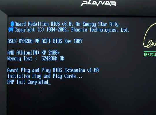 What if my motherboard isn't correctly identifying the processor? This happens all the time, and usually occurs for one of two reasons:
For more information on working with the motherboard's BIOS (Basic Input/Output System) menus, there's no better resource than the owners' manual (well, or maybe the Forums... if you need help, post in the Motherboards section) : ) 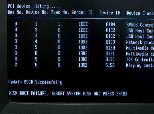 Since there are no bootable devices connected to the motherboard yet, I can expect this message for now. No worries. After bench-testing the motherboard/CPU/memory/video setup outside the case on cardboard, I do a reality check to make sure the standoffs are positioned to match the holes in the motherboard. Next, I gently lay the motherboard on the standoffs and ease its jacks through the I/O shield. 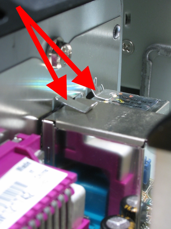 The red arrow shows an EMI spring that's intended to rest on top of the jack block. These tend to dive down into the jacks instead, so keep an eye on them as you bring the motherboard in underneath them. Click the picture for a close-up view of the EMI springs I'm talking about. As you push the motherboard against the I/O shield, the springy EMI springs will resist. Be careful not to use the CPU heatsink or the motherboard's smaller heatsink as handles as you overcome the resistance of the EMI springs; press against the opposite edge of the motherboard, or the jackblocks themselves, until you can get one or two screws in place. Look at the I/O shield from the rear, to confirm that no EMI springs sneaked into any jacks, then put in the motherboard screws and tighten them to a gentle firmness. Don't overtighten the screws, because you don't want crush the motherboard's electrical traces. So far, so good. Take a snack break and proceed on to the installation of the hard drive! : ) |