©
©
|
©
|
|
Previous: Caseprep, page 1
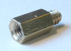
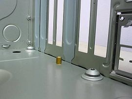
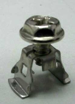
Back to the action I've unpacked the motherboard and noted its hole pattern, and now I'm screwing standoffs into the case in the necessary positions. Although the case has stamped markings to indicate the commonly-used hole patterns (ATX and microATX), you should still do a reality check... you do NOT want any standoffs in positions where the motherboard doesn't have a hole, or you'll probably have a short circuit and the computer will refuse to start. If your case uses brass standoffs, make them snug, but don't overtorque them and shear one off. 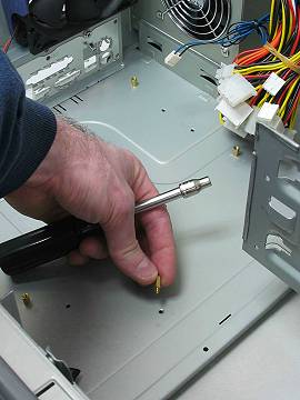 For illustration purposes, I'm going to take the I/O shield out of the rear of the case, compare it to the motherboard's jack layout, and pry out some knockouts to accomodate the motherboard's jack pattern. On this case, the I/O shield is held in place by a pair of screws, but it's more common for them to be pressed into place. 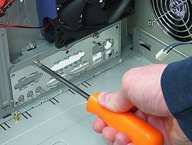 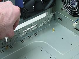 I'm removing the I/O shield's knockouts to accomodate the motherboard's jacks. If the motherboard has an unusual jack arrangement that the case's own I/O shield doesn't allow for, then use the I/O shield that comes with the motherboard. Press-fit it firmly into place from the interior of the case. 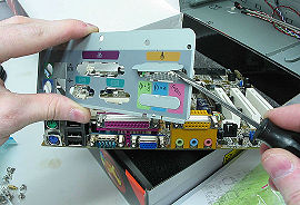 That looks good. 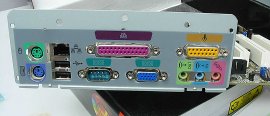 Before putting the I/O shield back in, I took this side shot of it so you can see the side that goes against the motherboard. See all those springy finger things? They're called "EMI springs." Take note of those, because I'll have a couple remarks about them when it's time to install the motherboard. Their purpose is to maintain lots of points of electrical contact with the motherboard's jacks, to prevent any long gaps that would allow excessive EMI leakage (EMI being electromagnetic interference). 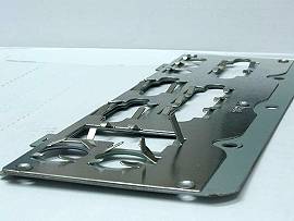 As I mentioned before, most cases (and all motherboards) come with press-in, spring-edged I/O shields. Here are a couple photos of the press-in type. You can see how the nubs on the edges grip the edge of the case's rectangular hole. Remember, these can be quite sharp! 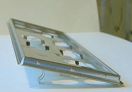 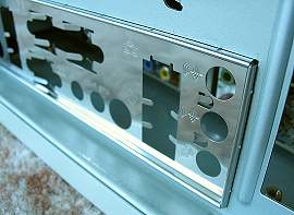 That completes the case preparations. Next: Data & power cables |